Seagate Manual
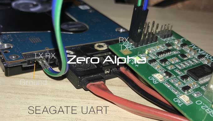
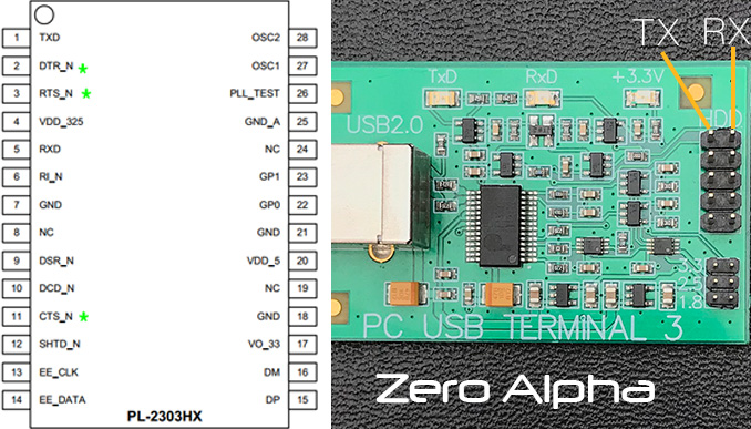
Terminal connection


Techmode Patch Script In Data Extractor Task
If the drive goes constantly busy and switches itself off,but you have to techmode patch it,you can make a script in Data Extractor Parameters:
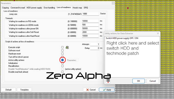
Go to Loss of Readiness -> Active Utility Actions (Parameters)->In pop-up window right click and select Switch HDD power supply OFF/On and right Click again and select Techmode patch.
Now when you are trying to read and drive goes busy this script will be executed. Make sure you have 1 in Attempts!
You can also turn on Software and Hardware reset.
Seagate Data Recovery Log
18FEB22 - ST4000LM024 MHA SWAP Drive. Diagnostic port locked. Used shorting points during techmode unlock patch.
|
patient |
donor |
|
Model : ST4000LM024-2AN17V |
Model : ST4000LM024-2AN17V |
| Model : ST2000LM007-1R8174-570 Serial : ZDZKRRV0 Firmware : EB01 Capacity : 2TB Site: TK Date: 11DEC2021 |
Model : ST2000LM007-1R8174-570 |
| Grenada | |
|
Model : ST2000DM001-1CH164-510 |
Model : ST2000DM001-1CH164-306 |
|
Model : ST2000DX001-1NS164-300 |
Model : ST2000DM001-1NS164-300 |
|
Model : ST2000DM001-9YN164-570 |
Model : ST2000DM001-9YN164-501 |
|
Model : ST3000DM001-1ER166-501 |
Model : ST3000DM001-1ER166-501 |
|
Model : ST2000DX002 |
Model : ST2000DX002 |
|
Model : ST8000DM004 |
Model : ST8000DM004 |
|
Model : ST2000DM001 |
Model : ST2000DM001 |
|
Model : ST3000DM001-1ER166 |
Model : ST3000DM001-1ER166 |
|
Model : ST3000DM001 |
Model : ST3000DM001 |
|
Model : ST1000LM035 |
Model : ST1000LM035 |
|
Model : ST3000DM001 |
Model : ST3000DM001 |
|
Model : ST6000DM003 |
Model : ST6000DM003 |
|
Model : ST1000LM035 3 heads Head vendor.............. : default Logical head map......... : 01 02 03 03 |
Model : ST2000LM007-1R8174 PreampType: 82 12 4 heads Head vendor.............. : default Logical head map......... : 00 01 02 03 |
|
Model : ST1000LM035 3 heads Head vendor.............. : default Logical head map......... : 01 02 03 03 |
Model : ST2000LM007-1R8174 4 heads Head vendor.............. : default Logical head map......... : 00 01 02 03 |
|
Model : ST4000LM024 max head 7, 12 heads Head vendor.............. : default Logical head map......... : 00 01 02 03 04 05 06 07 08 09 |
Model : ST4000LM024 max head 7, 12 heads Head vendor.............. : default Logical head map......... : 00 01 02 03 04 05 06 07 08 09 |
|
Model : ST4000LM024 max head 7, 12 heads Head vendor.............. : default Logical head map......... : 00 01 02 03 04 05 06 07 08 09 |
Model : ST4000LM024 max head 7, 12 heads Head vendor.............. : default Logical head map......... : 00 01 02 03 04 05 06 07 08 09 |
|
Model : ST2000DM001 max head: 3 heads count: 4 Head vendor.............. : default Preamp type.............. : 06CB Logical head map......... : 00 01 02 03 04 05 06 07 08 09 |
Model : ST2000DM001 max head: 3 heads count: 4 Head vendor.............. : default Preamp type.............. : 06CB Logical head map......... : 00 01 02 03 04 05 06 07 08 09 |
|
Model : ST8000DM004-2CX188 Product of China Fam ID................... : 0x9B (V11) |
Model : ST8000DM004-2CX188 Product of China Fam ID................... : 0x9B (V11) |
Seagate Diagnostic Commands
Upon power up, the drive will respond to a set of diagnostic command send through serial port. Because of the number of commands supported, the commands are broken up into ‘Levels’. Many, the progress may be sent over the serial port for number of bits written and read, and command such as read, write, seek, and error log manipulation are available at several different levels. Diagnostic commands are used in place of ATI scripts to do testing. While the drive is running these diagnostic commandshard/soft error rates, a number indicating the test currently being performed, and various information for status of the current test.
The firmware consists of 2 flash codes and numerous supporting files. The two flash codes are known as factory code and customer code. The factory code contains all the serial port diagnostics command but no AT interface command. The customer code contains all AT interface command but minimal set of serial port diagnostics command.
In the ‘Availability’ column, a ‘F’, ‘C’ and ‘B’ indicate the command is available at ‘Factory Code’, ‘Customer Code’ and ‘Both codes’ respectively.
The following is a short list of some of the serial port commands:
Level T - Certification Tests.
Download code
Start manufacturing test
Set drive ‘Age’
Commands to read cert logs, read error logs, write test data to flash, etc.
Level 1 - Memory Control Commands.
Commands to display buffer, display memory, set memory, copy buffer to flash, read sysvars from disk, etc.
Level 2 - Drive Level Commands
A command to configure the cylinders, heads for testing, gives option for random cylinder/head and random data patterns
Commands to set data patterns, perform ECC tests, manipulate the error log, dump the sequencer ram.
Commands to do physical to logical conversion, assign skips and alternates, etc.
Commands to spinup, spindown, seek, read, write, read long, write long, read compare, sleep, set retries, etc.
Level 3 - Seeking Commands
Display the zone table
Motor acceleration test
Measure head switch & settling times
Display head offset
Move actuator open loop
Seek, seek physical, varying length seek test
Latch test
Display position of actuator
Hysteresis test
Latch Exerciser test
Level 4 - Servo Tracking Commands
Manipulate a skipped cylinder table
Tracking error test
Display position error signal
Zap servo burst
Set servo offset
Set/display tracking gain
Send impulse to actuator
Уровень 5. Используется только в заводских условиях
Уровень 6 – Команды batch файлов
Batch файлы для тестирования запусков-остановок, переключения головок, CSS, тестов 1, 2, 3 коррекции burts, files to test start-stop, head switch, CSS, 1,2,or 3 burst correction test, назначаемые тесты, тесты сравнения данных, возможность вводить различные batch файлы в RAM.
Level 7 - Adaptive Control Commands
Tune parameter control and display
Diagnostic read track
AGC gain control
Perform VCO calibration for all zones
Level 8 - Special Packwriter Commands
- Servo diagnostic sub commands
- Configuration commands
- Lock spin external, spin speed adjust
- Set actuator bias current
Level 9 – Drive Level Command (Full-slipping Defect Management Mode)
Beside the above nine levels of commands, there are two additional sets of commands, the On-line commands and Common commands. The main purpose of On-line command is to display varies type of status. Common command is use to ‘poke’ and ‘peek’ into memoery to allow access to registers, buffer memory and data memory.
Seagate On-line Commands
The On-Line commands may be initiated at any time. For the Interface-specific commands, the Interface code must be present in the current memory map for successful execution; the General commands are always available.
Interface-Specific Commands
|
Command |
Description |
Availability |
|
^E |
Interface State: Max C.H.S. / RW multiple block size / Current transfer mode settings |
B |
|
^F |
Read Segment Record(s) |
B |
|
^G |
Write Queue Dump |
B |
|
^I |
Controller Register Dump ** (See figure 2.1.7) |
B |
|
^K |
Reserved |
|
|
^Q |
Reserved |
|
|
^R |
Reserved. This command can only be used when the drive is spun down |
|
|
^S |
Snapshot current execution address |
B |
|
^V |
Interface Command Echo and Activity Trace Toggle |
B |
|
^X |
Interface and Niwot Command History ** (See figure 2.1.6) |
B |
|
^Y |
Display Raw SMART Values (used for computing SMART Attributes) |
B |
|
‘~’ |
Interface Command State |
B |
|
|
|
|
Seagate General Commands
|
Command |
Description |
Availability |
|
^B |
(Reserved for Servo Use) |
F |
|
^D / ^N |
Retry Activity Display Toggle.
A message will be displayed as follows: e c r = 0 1 0
where ‘e’ = error tracing, ‘c’ = command tracing & ‘r’ = retry tracing. 0=disable, 1=enable.
When enabled causes the following characters to be sent to the serial port: ‘.’ = First data retry ‘,’ = subsquent data retry ‘c’ = Successful On-The-Fly correction occurred ‘f’ = Shifted Header retry. ‘H’ = Header retry ‘I’ = Sequencer was force-stopped. ‘s’ = Servo Recovery ‘w’ = Write Retry ‘+’ = Index active on non-index sector ‘D’ = Spin speed outside of tolerance ‘L’ = Latch retry ‘X’ = Resync servo bursts ‘<’ = Fine Track window exceeded. ‘$’ = Missing servo burst mark. |
B |
|
^L |
Display Sign-on Message, including firmware version. |
B |
|
^O |
Advanced Servo Tracing |
B |
|
^P |
Power Chop enable/disable toggle. |
B |
|
^T |
Restart Test. Causes the drive to restart testing at the current age. |
B |
|
^C |
Software Reset Command, Causes the drive to spin down re-initialize itself, spin backup, and come ready again. |
B |
|
^Z |
Restart the Diagnostic Monitor. |
B |
|
! |
Display Current R/W Channel Settings |
B |
|
% |
Show Mux Status. ** (See figure 2.1.1) |
B |
|
‘ |
Display Transfer Status (See figure 2.1.2) |
B |
|
. |
Display Active Status. ** (See figure 2.1.3) |
B |
|
; |
Display Machine Status. ** (See figure 2.1.4) |
B |
|
< |
Decrement read/write scope synchronization pulse position. |
B |
|
> |
Increment read/write scope synchronization pulse position. |
B |
|
? |
Show Buffer Allocation. ** (See figure 2.1.5) |
B |
|
^ |
Show Elapsed Time since start of cert test or last ^Z. |
B |
|
` |
Show Read/Write Statistics. |
B |
|
{ |
(Reserved for Servo Diagnostic Use) |
B |
|
} |
(Reserved for Servo Diagnostic Use) |
B |
|
ESC |
Interrupt Loop or Batch file execution. |
B |
|
= |
Display power up time |
B |
Figure 2.1.1: ‘%’ command display format
Returned data format:
aabbccccddeeffgg AX'iiiiiiii ' “jjjjjjjjjjjj’
|
aa |
Age |
|
bb |
Program |
|
cccc |
Accumulated health |
|
dd |
Drive type |
|
ee |
This is the Atlantis ECA0h WRSTATS register value |
|
ff |
Error code byte |
|
gg |
Maximum number of heads for this type |
|
iiiiiiii |
Drive serial number |
|
jjjjjjjjjjjj |
PCBA serial number |
Figure 2.1.2: ‘ ‘ ’ command display format
Returned data format:
Cmd Cyl Hd Sct Cnt Stbuf Segl Csct Cbuf Actv Ercd Rtry Flags
aa bbbb cc dddd eeee ffff gg hhhh iiii j kk mmmm.nn.pp qq
|
Cmd aa |
Last command type |
|
Cyl bbbb |
Cylinder of current command |
|
Hd cc |
Head of current command |
|
Sct dddd |
Start sector of current command |
|
Cnt eeee |
Length or block count |
|
Stbuf ffff |
Start buffer number |
|
Segl gg |
Buffer size
|
|
Csct hhhh |
Current Sector |
|
Cbuf iiii |
‘Intfwork1’ address |
|
Actv j |
CIP |
|
Ercd kk |
Error Code |
|
Rtry mmmm.nn.pp |
Retry parameters (see level 2 Y command) mmmm - retry control bit nn – read retries count pp - write retries count |
|
Flags qq |
R/W flags |
Figure 2.1.3: ‘ . ’ command display format
Returned data format:
Pgm=aa Trk=bbbb(cccc).d.eee Zn=f Err=gg ErCt=hhhh Hlth=iiii Chlth=jjjj Ready
|
Pgm=aa |
Active program 00 is diagnostic monitor. 50 is interface program All other numbers are current test running. |
|
Trk=bbbb(cccc).d.eee |
Currently selected logical cylinder (physical cylinder), head, sector. |
|
Zn=f |
Zone |
|
Err=gg |
Error code from current operation |
|
ErCt=hhhh |
Error count since last reset of drive or last reset error log command |
|
Hlth=iiii |
Accumulated health bits - four digits |
|
CHlth=jjjj |
Current health bits – four digits |
|
Ready |
Drive status. Can be Ready or Ntrdy
|
Figure 2.1.4: ‘ ; ’ command display format
Returned data format:
Age=aa Type=bb MxCyl=cccc MxHd=d MxSct=eee Bsz=ffff TCode=gggg
|
Age=aa |
Current drive age |
|
Type=bb |
Current drive type |
|
MxCyl=cccc |
Maximum cylinders for this drive type in hex |
|
MxHd=d |
Maximum heads for this drive type in hex |
|
MxSct=eee |
Maximum Sector for this drive type in hex |
|
BSz=ffff |
Buffer size in hex |
|
Tcode=gggg |
Test code for T.E. Hda Test |
Figure 2.1.5: ‘ ? ’ command display format
Returned data format:
RD:xxxx:yy
WR:xxxx:yy
AC:xxxx:yy
AS:xxxx:yy
DP:xxxx:yy
BA:xxxx:yy
ST:xxxx:yy
logbps:xxxx
codebps: xxxx
uP:xxxx:yy
CO:xxxx, yy
FM:xxxx:yy
AD:xxxx:yy
|
RDxxxx:yy |
xxxx = Buffer number for read buffer yy = Buffer size in sectors |
|
WR:xxxx:yy |
xxxx = Buffer number for write buffer yy = Buffer size in sectors |
|
AC:xxxx:yy |
xxxx Buffer number for active log buffer yy = Buffer size in sectors |
|
AS:xxxx:yy |
xxxx= Buffer number for ascii log buffer yy = Buffer size in sectors |
|
DB:xxxx:yy |
xxxx = Buffer number for display log buffer yy = Buffer size in sectors |
|
BA:xxxx:yy |
xxxx = Buffer number for batch file buffer yy = Buffer size in sectors |
|
ST:xxxx:yy |
xxxx = Buffer number for statistics log buffer yy = Buffer size in sectors |
|
logpbs:xxxx |
Bytes per sector in cert log area |
|
codebps:xxxx |
Bytes per sector in code area |
|
uP:xxxx:yy |
xxxx = Buffer number for microprocessor ram yy = Buffer size in sectors |
|
CO:xxxx, yy |
xxxx = First code buffer address yy = reserved |
|
FM:xxxx:yy |
xxxx=Buffer number for format operations (moving alts) yy=Buffer size in sectors |
|
AD:xxxx:yy |
xxxx=Buffer number for reading/saving adaptives yy=Buffer size in sectors |
Seagate Common Commands:(Available from All Levels)
The Common Commands may be executed whenever the diagnostic monitor prompt is present and the monitor is waiting for a command request.
The ‘-‘ and ‘=’ commands involves access of absolute address inside the embedded environment. Each address has 20-bit address. Please get the memory map from DE.
In the ‘Availability’ column, a ‘F’, ‘C’ and ‘B’ indicate the command is available at ‘Factory Code’, ‘Customer Code’ and ‘Both codes’ respectively. Besides, a ‘P’, ‘S’, and ‘*’ denote the command is available only if the code is compiled in ‘Packwriter Mode’, ‘Servo Mode’ and ‘Special Mode’ respectively.
|
Command |
Description |
Avail. |
|
CR |
Loop Break. |
B |
|
*
|
Special Function for batch file: *1 = Pause batch file execution until input *2,x = Delay x milliseconds *3,x = Branch to Label x *4,x = Increment head and branch to Label x *5 = Clear monitor screen *6 = Stop on error *7,x = Load batch loop counter with x *8, x = Decrement batch loop counter, branch to label x if 0, |
B |
|
+x,yyyy |
Peek Byte. Display the byte data content of the specified memory address. |
B |
|
+xyyyy |
Peek Byte. x - upper bits of a greater-than-16 bit address |
B |
|
+yyyy |
Peek Byte. yyyy - lower 16 bits address. The high address in previous x,yyyy is used. |
B |
|
/x |
Change Level to Diagnostic Monitor Level x. |
B |
|
=x,yyyy,zz |
Poke Byte. Replace the contents of the specified address with the specified data. Note that non-volatile area cannot be modified by this command. zz – byte data content to be written at the specified address |
B |
|
=xyyyy,zz |
Poke Byte. Replace the contents of the specified address with the specified data. Note that non-volatile area cannot be modified by this command. zz – byte data content to be written at the specified address |
B |
|
=yyyy,zz |
Poke byte. Replace the contents of the speficied address with the specified data. yyyy – lower 16-bit address. The high address in previous x,yyyy is used. Note that non-volatile area cannot be modified by this command. zz – byte data content to be written at the specified address |
B |
|
@x |
Label. During batch file entry, define this location as Label x, where x = single digit numeric label specification. |
B |
|
Peek Word. Display the word contents of the specified address. x – upper bits of 20-bit address yyyy – lower 16 bits of 20-bit address |
B |
|
|
Axx |
Set Test Space. Next command to repeat execution as specified by xx: Bit 7 6 5 4 3 2 1 0 . . . . . . . +-- 1=all head, 0=current head . . . . . . +---- 1=all cyl, 0=current cyl . . . . . +------ 1=random cyl/hd, 0=sequential cyl/hd . . . . +-------- 1=set special (see below) . . . +---------- 1=even cyl, 0=all cyl . . +------------ 1=odd cyl, 0=all cyl . +-------------- 1=sequential out, 0=sequential in +---------------- 1=random data, 0=existing buffer data
xx – if not present, display current test space.
Special setting: A8,yyyy = Set minimum cylinder to yyyy A9,yyyy = Set maximum cylinder to yyyy AA,y = Set maximum head to y AB,y = Set minimum head to y AC,yyyy = Set command timeout to yyyy ms AD = Set mins/maxs to defaults
|
B |
Seagate Level T Commands
|
Command |
Description |
Avail. |
|
Bxxx |
Set Baud Rate xx baud rate 1152 115.2k 625 62.5k 576 57.6k 384 38.4k 288 28.8k 192 19.2k 96 96.k 48 4.8k |
B |
|
Reset Certification Test. Resets health bits and sets age to 1. |
B |
|
|
Dxx,yy,zz |
Display Cert Logs sequentially from Log xx.
xx – Log to start sequential display; if blank, display only logs of failed tests.
yy – Displays only log entries with this error code If yy = AA, enables Special Log Controls zz.
zz – Special function: If zz = 40 - Enable fast dump capability for data cataloger capture. Inhibits time delay between log dumps and enables fast, unformatted log dump |
B |
|
Exx,yy,zz |
Display/Edit Cert Log(s)
xx - Log number to display (no entry) Display Active Log = 0 - Clear Active Log <> 0 - Display Log xx
yy - Displays only log entries with this error code If yy = AA, enables Special Log Controls zz.
zz - Special function: = 08 – Clear and insert ASCII characters from serial port into ASCII log. When CR is entered, save to Log xx and close ASCII Log. = 10 - Append characters from serial port to ASCII Log xx. Close on receipt of CR. = 20 – Write Active Log to Log xx. = 40 – Enable fast dump capability for data cataloger capture. Inhibits time delay between log dumps and enables fast, unformatted log dump. = 80 – Display address of Log xx (Formerly zz = FF) |
B |
|
Gx,y |
Read/Write critical component vendor sector
x = which vendor sector y = if not specified: read, specified: write |
B |
|
Hxx,yy,zz
|
Display/Reset Health Status Bits.
xx - (anything entered) - Display Current Health - (nothing entered) - Display Accumulated Health
yy - (not used)
zz - =22h => Reset both current and accumulated health to 0000. |
B |
|
I |
Cert the reserved cyl |
F |
|
Jxx,yy |
Set Scope Sync from Cert Log entries:
xx - Use entries from Cert Log xx; Blank => Use Active Log. yy - Blank => all entries; yy = sync only on Error Code yy entries. |
B |
|
Nxx |
Set Drive Age to xx. |
B |
|
R |
Read System Sector into System RAM |
B |
|
Txx |
Run Factory Test xx |
B |
|
Wxx,yy,zz |
Save System RAM into System Sector.
If age <> 60 then xx,yy,zz is not used. If age == 60 then xx - (not used) yy - (not used) zz - =22h => Reset Adaptives |
B |
|
Yxx |
Set Drive Type to xx.
Sets drive type to its default configuration stated below. All defect tables and tuned read/write parameters will be initialised by this command. For safety reasons, this command does not write drive type to system tracks. A W must be issued to write the information to the drive.
xx = E0: 1 header version = E1: 2 header version = E2: 3 header version = E3: 4 header version |
B |
|
dxx |
Download CERT, RWF, CSPT, DEF from Serial Port to Buffer then write to reserved cyl.
xx = - FILEKEY for downloading.
1H OVLY_CCT 2H OVLY_ACT 3H OVLY_XX 4H DEFRSV 5H DEFFTY 6H DEFUSR 7H DEFLZT 8H RWF 9H SYSVAR1 AH SYSVAR2 BH CSPT CH VBPI DH FLSH_AT EH FLSH_CT 0FH AT_STUFF 10H SECURITY 11H VENDOR_SPEC 12H SMART ATTRIBUTE 13H SMART THRESHHOLD 14H SMART DIRECTORY 15H SMART ERROR LOG 16H SMART COMPREHENSIVE LOG 17H SMART SELF_TEST_LOG 18H SMART CRITICAL_EVENT_LOG 19H SMART HEALTH_LOG 1AH SMART DRIVE_VENDOR_LOG 1BH SMART HOST_SPECIFIC_LOG 1CH WRITE_PROTECT 1DH CON GEN 1EH SKIP CYLINDER LIST
= 8X – For DLE only, ie. Only downloaded to buffer Ram. = 88 – DLE only for RWF. = 8B – DLE only for CSPT
|
|
|
uxx |
Upload CERT, RWF, CSPT, DEF from Serial Port to Buffer then write from resv
Performs the uploading of files from the reserve tracks. The keys are exact the same as those in the download command. |
B |
|
fxxxx,yyyy |
Download new flash code from Serial Port to Buffer then burn it in
xxxx - Algorithm Selector Word (ASW) yyyy - None zero number will program this as the User Default ASW (See figure 2.3.1 for ASW bits definitions)
(a) if xxxx is not specified => a.1) if default ASW is 0 or ffffh => current ASW is obtained from table, next ASW = ffffh a.2) if default ASW is other values => current ASW = next ASW = default ASW
(b) if xxxx is specified => b.1) if yyyy is 0 => next ASW is default ASW, current ASW = xxxx b.2) if yyyy is ffffh => next ASW is default ASW, current ASW = xxxx b.3) if all other yyyy values => next ASW = xxxx, current ASW = xxxx |
B |
|
# |
Enter HDA Serial Number.
The S/N may be up to 8 A/N characters long, left justified, and right padded with spaces until string length is 8 characters. |
B |
|
[x |
ASCII Log Control:
x = A Enables ASCII logging x = B Disables ASCII logging x = D Displays ASCII log |
B |
|
|
|
|
|
|
|
|
|
|
|
|
ASW WORD
The Algorithm Selector Word (ASW) is a command to tell the flash upgrade routine to select the correct flash programming algorithm. It can be issued as a parameter in the SDLE.EXE software. The idea is to have single generic routine to cater for different flash memory programming algorithm. Typical flash programming involves ‘word programming’ and ‘sector programming’. If a new flash vendor is cut in, the firmware is not required to change. Just use the correct ASW will do.
Figure 2.3.1
Low Byte
|
7 |
6 |
5 |
4 |
3 |
2 |
1 |
0 |
|
Future use |
Future use |
Future use |
Future use |
Future use |
Future use |
Word Programming |
Reserved (was 128-word pgm) |
High Byte
|
15 |
14 |
13 |
12 |
11 |
10 |
9 |
8 |
|
Chip Erase & Reprogram |
Main Memory Erase & Reprogram |
Future Expansion |
Future Expansion |
Future Expansion |
Future Expansion |
Future Expansion |
Future Expansion |
Seagate Level 1 Commands: Memory Manipulation Commands
In the ‘Availability’ column, a ‘F’, ‘C’ and ‘B’ indicate the command is available at ‘Factory Code’, ‘Customer Code’ and ‘Both codes’ respectively. Besides, a ‘P’, ‘S’, and ‘*’ denote the command is available only if the code is compiled in ‘Packwriter Mode’, ‘Servo Mode’ and ‘Special Mode’ respectively.
|
Command |
Description |
Avail. |
|
Bxx,yy |
Buffer Display
xx - Buffer number to display. Note: If the displayed buffer is a read buffer, then low-lighted bytes which do not compare to the corresponding write buffer. yy - Buffer number to compare data to (non matching data is high-lighted). If xx is a read buffer and yy is not entered, data matching the corresponding write buffer location is low-lighted; non matches are high-lighted.
|
B |
|
Dx,yyyy,zz |
Display Memory.
Displays 256 bytes of memory starting at address xyyyy. x - upper bits of >16 bit address yyyy - lower 16 bits of >16 bit address or the 16 bit address zz - high-light bytes matching this value. |
B |
|
E |
Erase System Information- Set all parameters to defaults.
*** Drive must be power cycled for this command to take effect |
B |
|
F |
Read jumper infomation.
Returns message: Jumper: yy
yy = 00: Slave (no jumper installed) yy = 01: Master with ATA slave or single drive (jumper near ATA cable installed) yy = 02: Cable Select (jumper near serial connector installed) yy = 03: Master with non-ATA slave (both jumper installed) |
B |
|
M |
Show Flash ROM Device Code, Manufacturer Code, User Default Algorithm Selector Word (ASW), and Fallback Default ASW. Drive will reboot after finishing this command. |
B |
|
Nxx |
SMART Serial Port Control
xx – Level 1 N Subcommand = 1 – Create Smart Sector. = 2 – Update SMART Attributes ( same as SMART D3h option in interface ) = 3 – Do Smart Firmware Upgrade = 5 – Dump SMART attribute data = 6 – Dump SMART threshold data = 7 – Dump G-List = 8 – Dump Critical Event Log = 9 – Dump P-List = A – Dump two hour Health Log = B – Run DST Short Test = C – Run DST Long Test |
B |
|
Sx,yyyy |
Edit Memory Byte.
x - upper bits of >16 bit address yyyy – lower 16 bits of >16 bit address or the 16 bit address The uP will continue to read the memory byte and will update the display if the byte changes. After entering desired edit value, the following actions may be taken: DEL - Re-edit same byte CR(^M) - Close out and exit LF(^J) - Edit the next sequential location |
B |
|
Ux,yyyy |
Edit Buffer Byte.
This is the same command as S except the Buffer Memory is edited. |
B |
|
Vxx,yy,zz |
Verify and count the number good copies of CERT, RWF, CSPT, DEF in Reserve xx = - FILEKEY for verifying (same as level T, d command, except the following, which are not supported) = 0D – CERT FLSH (for auto reflash) = 0E – AT FLSH (for auto reflash) = 0F – AT_STUFF = 10 – Security (not used, as it is auto downloaded by drive firmware) = 11 – Vendor Specific Entry = 12 ~ 1B – SMART related entries = 1C - Write Protect = 1E – SKIP_TRK
Note: Although the number of good copies valid might be displayed for the above FILEKEYs, these are strictly not valid.
yy = - Not entered for just counting the number of good copies available. - If entered, is the Copy Number, which is reserved for DE internal use only.
Zz = - Not entered for just counting the number of good copies available. - If entered, is the Head Number, which is reserved for DE internal use only. |
B |
|
W |
Compare PCB serial number with system sector’s serial number
If both serial number are equal, print “01”. If not, print “00”. This feature is for process to detect if PCB has been swapped across HDA. |
B |
|
Yxxxx |
Converts desired cylinder number to gray code and display the result. xxxx - specifies the cylinder number to convert. |
B |
|
fxxxx |
Program the FlashROM with either AT- or CERT-built code stored on the reserved tracks
xxxx = AAAA Flash with AT (customer) code xxxx = CCCC Flash with CERT (factory) code
Use SDLE to download the code files onto the reserved tracks. |
B |
|
mx,yyyy |
Edit memory word. Operates same as level 1 ‘S’ command, except operates on words. |
B |
|
yxxxx |
Converts desired gray code to a cylinder number and displays the result. xxxx - specifies the gray code to convert |
B |
|
$ |
Set PCB information and update flash
The user will be prompted to enter PCB EC#, PCB S/N and PCB P/N. This feature is used by PCB plant to burn in PCB#, EC# and serial #. Then the drive plant will automatically retreive the information. |
B |
|
# |
Display PCB information
Display the PCB information burnt by $ command. |
B |
Seagate Level 2 Commands: Niwot Read/Write Commands
In the ‘Availability’ column, a ‘F’, ‘C’ and ‘B’ indicate the command is available at ‘Factory Code’, ‘Customer Code’ and ‘Both codes’ respectively. Besides, a ‘P’, ‘S’, and ‘*’ denote the command is available only if the code is compiled in ‘Packwriter Mode’, ‘Servo Mode’ and ‘Special Mode’ respectively.
|
Command |
Description |
Avail. |
|
Bxx,yy |
Display Buffer
xx = 512 byte buffer number yy = buffer number for Data match. If xx is a read buffer and yy is not entered, data matching the corresponding write buffer location is low-lighted; non matches are high-lighted. |
B |
|
Cxx,yy,zz |
Copy Buffers
xx = Source buffer for the data. yy = Destination buffer of the data. zz = number of 512 byte buffers to copy (1 is default) |
B |
|
Exx,yy,zz |
Display/Edit Cert Log(s)
xx - Log number to display. - If no entry, Display Active Log = 0 - Clear Active Log <> 0 - Display Log xx
yy - Displays only log entries which have Error Code yy. If yy = AA, enables Special Log Controls zz.
zz - Special Log Controls: = 08 – Clear and insert ASCII characters from serial port into ASCII log. When CR is entered, save to Log xx and close ASCII Log. = 10 - Append characters from serial port to ASCII Log xx. Close on receipt of CR. = 20 – Write Active Log to Log xx. = 40 – Enable fast dump capability for data cataloger capture. Inhibits time delay between log dumps and enables fast, unformatted log dump. = 80 – Display address of Log xx (Formerly zz = FF) |
B |
|
Hx |
Select Head xx - Head to Select. |
B |
|
Ixx,yy,zz |
Display/Modify Adaptive Settings.
(no parameters) – Display current heads adaptive values xx - zone number yy - parameter number to modify zz - value to assign to parameter yy |
B |
|
Jxx,yy |
Scope Sync from Log.
xx - cert log number to take entries from - Default: use Active Log yy - sync only on entries with this error code. |
B |
|
Kxxxx,y |
Set Tracking Offset
xxxx - signed, 16 bit integer in units of 265/band (band = 2/3 track). Default = 0. y = 0 : xxxx is temporary offset and is cleared with next seek. Default = temporary. y = 1 : xxxx is persistent offset and is cleared on power cycle or servo cal. |
B |
|
Lxx,yyyy
OR
Lxx,zz,yyyy |
Loop. Causes the next command to repeat execution, subject to controls specified by xx , yyyy and zz
Bit 7 6 5 4 3 2 1 0 . . . . . . . +------ 1 = Continue on error, 0 = Stop on error . . . . . . +-------- 1 = Stop on no error . . . . . +---------- 1 = Spindown on error, 0 = don’t spindown on error . . . . +------------ 1 = Reserved . . . +-------------- 1 = Inhibit err msg on error . . +---------------- 1 = Stop on error code=yyyy, 0 = Loop count . +------------------ 1 = Looping primed (internal use) +-------------------- 1 = Looping active (internal use)
yyyy = Error code to stop or Loop count zz = Hi-byte of loop count
For example: L1,12,3456 - Don't stop on error , loop for 123456h times L0,78 - Stop on error or repeat for 78h times whichever comes first. L2 - Stop on NO error L20,43 - Stop on error code 43h. L24,43 - Stop on error code 43h., spindown drive when stop L30,43 - Stop on error code 43h, disable error messages display .
|
B |
|
Oxxxx,yyyy,zzzz |
Seek-Seek on current head:
xxxx - Cylinder to seek from. Default is MinCyl yyyy - Cylinder to seek to. Default is MaxCyl zzzz - Number of seeks to perform. Default: continue until next keyboard entry |
B |
|
Pxxxx,yy,zz |
Set Buffer Pattern. Note : yyyy and zzzz formats will depend on xx
xx - Pattern options to write into buffer. - 8100 = incrementing pattern - 8200= random pattern - 8400 = isolating pulse pattern - 9400= fill buffer memory with the 16-byte memory array yyyy - buffer number to fill, default all write buffer zzzz - ignored xx - NN = defined buffer number to fill with the pattern - 9000 = fill the 16 bytes memory array with pattern - 9100 = fill last 12 bytes of memory array with pattern - 9200 = fill last 8 bytes of memory array with pattern - 9300 = fill last 4 bytes of memory array with pattern yyyy - lower word of pattern to fill zzzz - higher word of pattern to fill
Example : P8200,1F -- fill buffer number 1Fh with random pattern P8100 -- fill enitre write buffer with incrementing pattern -------------------------------------------------------------------------------------- P,1234,5678 – fill entire wrtie buffer with ‘12345678’ P0A,2222 -- fill buffer number 0Ah with pattern ‘2222’ -------------------------------------------------------------------------------------- P9000,0000,0000 -- fill 16-byte memory array with 0s P9100,0000,0000 -- fill last 12 bytes of memory arrary with 0s P9200,FFFF,FFFF -- fill last 8 bytes of memory array with ‘F’s P9300,FFFF,FFFF -- fill last 4 bytes of memory array with ‘F’s P9400,10 -- fill buffer 10h with pattern : (after cmd P90,P91,P92,P93) ‘0000 0000 0000 0000 FFFF FFFF FFFF FFFF’ P9400 -- fill entire write buffer with ‘0000 0000 0000 0000 FFFF FFFF FFFF FFFF’
|
B |
|
Qxx,yy |
Write/Read/Read Data.
xx - Start sector # on each track yy - Number of sectors to transfer (limited to # sectors remaining on track). Default: Number of sectors remaining on track. |
B |
|
Rxx,yy |
Read Data.
xx - Start sector number (default = 0) yy - Number of sectors to read . Default: Number of sectors remaining on this track. |
B |
|
Sxxxx,yy,zzzz |
Seek Cyl/Head.
xxxx - Cylinder number yy - Desired destination head. If the most significant bit is set, the command will seek to the physical cylinder number specified in the first parameter; else, the seek will be to the logical cylinder zzzz - Track follow offset. Signed 16 bit integer |
B |
|
Tx |
Measure Throughput.
x not entered: Measure Read Throughput x = 1 Measure Write Throughput |
B |
|
Uxx,yy |
Spin-Up
xx not entered: Normal spin-up until drive ready
xx value: - 0 spin up with no hold states - 1 advance hold state - 2 release all hold states - 3 hold in warm up state - 4 hold in buzz state - 5 hold in pre-lock state - 6 hold in lock state - all others = no hold state change
yy - Head number to use to go active. |
B |
|
Vxx,yy,zz |
Read/Compare against corresponding write buffer.
xx - Starting sector on each track (default 00) yy - Number of sectors to read (default is number remaining on track). zz - Buffer to compare data against. Default: first Write Buffer. |
B |
|
Wxx,yy |
Write Data.
xx - Starting sector on each track (default is 00) yy - Number of sectors to write (default is remainder of track) |
B |
|
Show/Set Retry Controls
xx (not entered) - Show current settings
Bit 15 14 13 12 11 10 09 08 . . . . . . . +-- VCO cal retry enable . . . . . . +------ Channel reload retry enable . . . . . +---------- Write splash retry enable . . . . +-------------- Early read retry enable . . . +------------------ Offtrack read retry enable . . +---------------------- Preamp Hi Gain retry enable . +-------------------------- TA retry enable +------------------------------ Erasure pointer retry enable
Bit 07 06 05 04 03 02 01 00 . . . . . . . +-- ECC level control bit 0 . . . . . . +----- ECC level control bit 1 . . . . . +--------- ECC level control bit 2 . . . . +------------- Max ECC retry enable . . . +----------------- Run out cal retry enable . . +--------------------- Servo Threshold retry enable . +------------------------- Boost retry enable +----------------------------- MR bias retry enable
yy – data retry count zz- ID retry count updated only when not 0 aa – write retry count |
B |
|
|
Z |
Spin-Down. |
B |
|
b |
Display Buffer Starts Displays the first two bytes of each sector-sized buffer. |
B |
|
cxx,yy |
Compare Buffers.
xx - Source buffer (default is first read buffer) yy - Reference buffer to compare against (default is first write buffer) |
B |
|
exx,yy |
Save Log to Cert Log yy.
xx - Source Log type: 0 = Active Log, 1 = ASCII log, 2 = Display log yy - Destination Cert Log number |
B |
|
hxxxx,yy,zz |
Translate Niwot CHS to Logical CHS. Maximum Niwot CHS allowed is NiwotCHS of (Stuff.TotalUserCapacity-1) .
Xxxx - Niwot cylinder yy - Niwot head zz - Niwot sector
- Algo: if (translated LBA <Stuff.TotalUserCapacity) { display LBA; if (Logical CHS < Stuff.CurrentAT CHS) display logical CHS; else display invalid CHS FFFF/ F/ FF; } else display Param Invalid; Examples: "h73,0,0" yields "0000000, 0000/ 0/ 00" "h31A,0,1B" "003E3FF, 00FF/ F/ 3E" -where "003E3FF" is LBA, and "00FF/ F/ 3E" is NiwotCHS "h434f,3,13f" "201F77F, FFFF/ F/ FF" -invalid CHS displayed as max logical geometry is 3FFE/F/3E
|
B |
|
lxxxx,yy,zz |
Translate Logical CHS /LBA to Niwot CHS
LogicalCHS i/p: xxxx - Logical cylinder yy - Logical head zz - Logical sector
LBA i/p: Xxxx - LBA hi-word Yy - LBA lo-word
Note: 1. All three input arguments start counting from zero 2. When no arguments are entered, max user LBA and its NiwotCHS are returned
Examples: 1. LogicalCHS to NiwotCHS "l0,0,0" yields "0000000, 0073/ 0/ 000" "lFF,F,3E" "003E3FF, 031A/ 0/ 01B" "l" "1F7F81F, 4233/ 2/ 10B" 2. LBA to NiwotCHS "l201,F77F" "201F77F, 434F/ 3/ 13F"
|
B |
|
rxx |
Read Long from current track Xx - Sector to read (including ECC Syndrome bytes) |
B |
|
t |
Returns number of physical sectors per track for the current track |
B |
|
u |
Unsleep.
Wakes the drive up, spins it up and makes it come ready. |
B |
|
vxx,yy |
Write-Read-Compare
xx – Starting sector on each track (default 00) yy – Number of sectors to write/read (default is number remaining on track). |
B |
|
wxx |
Write Long to current track
xx – Sector to write (including ECC Syndrome bytes) |
B |
|
x |
Show Zone Boundaries |
B |
|
y |
Show Retry Counters |
B |
|
zx |
Sleep.
x not sent - Standby Mode, Spin down, park heads, power off channel and pre-amp. x = 1 - Sleep Mode, in addition to above the buffer is powered down. Requires a power cycle to recover from this mode. |
B |
|
$xxxx |
Set sector per track for the entire drive. * xxxx - sector per track * This command is strictly for engineering puprposes only. Use at own risk |
B |
|
&xxxx,yy,zz |
& - Display current skew information and first sector next to index * xxxx = CADE followed by yy and zz to set skew. * xxxx = DEAD , perform write gate timing test. Destructive command! yy = head skew zz = cylinder skew · This command is strictly for engineering puprposes only. Use at own risk.
Examples: 1. Perform 63/62h error test 2>&DEAD <cr>
2. Display skew information 2>& <cr> CSkew = 16 Hskew = 13 CurSkew = 0039 IdxSec = 0164
3. Set HeadSkew=0 and CylSkew=1 2>&CADE,0,1 <cr> CSkew = 1 Hskew = 0 CurSkew = 0000 IdxSec = 0000
4. Display SPLITCNT 2>&1A <cr> 2>Split = 00DC ; sector 1A has split at byte DCh
2>&1C <cr> 2>Split = 0000 ; sector 1C has no split |
B |
Seagate Level 3 Commands: Servo Seeking Commands
In the ‘Availability’ column, a ‘F’, ‘C’ and ‘B’ indicate the command is available at ‘Factory Code’, ‘Customer Code’ and ‘Both codes’ respectively. Besides, a ‘P’, ‘S’, and ‘*’ denote the command is available only if the code is compiled in ‘Packwriter Mode’, ‘Servo Mode’ and ‘Special Mode’ respectively.
|
Command |
Description |
Avail. |
|
A |
Set Test Space Refer to ‘Common Command’ section for detail information |
B |
|
B |
Graphic Torque Constant Measures Acceleration Constant across entire pack and graphs the results. |
F |
|
Cxxxx,yyyy |
Acceleration Constant Measurement Test
xxxx - ID cylinder limit for test yyyy - OD cylinder limit for test Note: xxxx > yyyy |
B |
|
Dxx, yy, zzzz |
Access Times Measurement If bit7 of yy is 0, then do normal access time test xx : 1) xx=no entry, the access time test is on different seek length 2) xx=0, Random seek 3) others, xx denote as a seek length yy : 1) yy=no entry, assume yy=0 2) yy bit0 determines settling type [bit 0] = 0, denotes read settling [bit 0] = 1, denotes write settling 3) yy bit1 determines seek direction ( not valid for random seek) [bit 1] = 1, seek from RdWrMinCyl to RdWrMaxCyl [bit 1] = 1, seek from RdWrMaxCyl to RdWrMinCyl zzzz : specify the loop count ( default/no entry = 400h)
If bit 7 of yy is 1, then do head switch test at particular track xx : denotes the track where head switch will be done yy : bit0 determines settling type [bit 0] = 0, denotes read settling [bit 0] = 1, denotes write settling zzzz : specify the loop count (default/no entry = 400h) |
B |
|
Exxxx |
Display/Edit CertLog Refer level 2 for more detail information. |
B |
|
Gxxxx,yy |
Translate Hex to Gray xxxx – Cylinder number to translate to Gray yy – servo zone yy = 0 , access servo band < 16482 yy = 1 , access servo band > 16482 |
B |
|
Hx |
Head Select x - head to select |
B |
|
J,yy,zz |
Servo Settle/Head Switch Offset Test yy - test cylinder (current cylinder if no value entered) zz - settling limit (default = head_skew+4) |
B |
|
Kxx,yy,zz |
Head Settling Time xx – Offtrack disturbance amplitude yy –Track nos (default=75) zz – Start Head nos. (default=0) |
B |
|
Lxx |
Loop. See the same command in Level 2 |
B |
|
Mxx,yy |
Actuator Open-loop Move xx - DAC output value (max=1FFF Hex) yy - DAC control value (Drive specific)(Bit 0= 0 for in, Bit 0=1 for out) |
F |
|
Oxxxx,yyyy,zzzz |
Seek-Seek on current head: For x<y, use read settle. x>y, use write settle. xxxx - Cylinder to seek. Default: MinCyl yyyy - Cylinder to seek to. Default: MaxCyl zzzz - Number of seeks to perform. Default: 65536 cycle. Note: If ‘CHANGEKK013_00’ switch is not enabled, it perform normal seek-seek only. |
B |
|
Qxxxx,yyyy |
CertWrite Read xxxx –First sector (default=0) yyyy –Transfer length (default=full track) |
B |
|
Rxx,yyyy,zz |
ReadGrey xx –0 read for 1 sector; not 0 read for 1track. yyyy –Desired track zz –Desired sector |
B |
|
Sxxxx,yy,zzzz |
Seek Cyl/Head.
xxxx - Target cylinder number yy - Desired destination head. If the most significant bit is set, the command will seek to the physical cylinder number specified in the first parameter; else, the seek will be to the logical cylinder zzzz - Track follow offset. Signed 16 bit integer |
B |
|
T |
Servo Calibrations |
B |
|
Ux |
Spin-Up x – 0 = Spin up with no hold states 1 = advance hold state 2 = release all hold state 3 = hold in warm up state 4 = hold in buzz state 5 = hold in pre-lock state 6 = hold in lock state all other = no hold state change |
B |
|
W |
‘Where-is’ Actuator/Read Physical Grey |
B |
|
Y |
Hysteresis Performs Hysteresis test across the entire pack and displays the results graphically. In addition the inward seek integrator value is plotted.
* = Hysteresis value o = -Integrator value x = +Integrator value Note: Integrator values are scaled , /4 . |
B |
|
Z |
Spin-Down |
B |
|
gxxxx,yy |
Translate Gray to Hex xxxx - Gray code value to translate to Cylinder number yy - Servo zone
yy = 0 , access servo band < 16482 yy = 1 , access servo band > 16482 |
B |
|
jxxxx |
Latch Exerciser Test xxxx - No of times to do latch and unlatch process. |
|
|
k |
Measure head Offset position |
|
|
l |
Latch Test Perform spin down/ spin up for 8 times and output average value |
B |
|
lxxxx,yyyy,zzzz |
Latch Tuning Test xxxx = limit counter yyyy = acceleration frequency count zzzz = deceleration frequency count
Note: This command is enabled when LATCH_TEST_TUNING is turned on. |
* |
|
pxxxx,yy,zz |
Translate Niwot CHS to Logical CHS
xxxx - Niwot cylinder yy - Niwot head zz - Niwot sector |
B |
|
qxxxx,yy,zz |
Translate Logical CHS to Niwot CHS
xxxx - Logical cylinder yy - Logical head zz - Logical sector
Note: All three input arguments start counting from zero |
B |
|
sxxxx,yy,zzzz |
Seek to Physical Cylinder and Head, ignore Skipped Cylinder xxxx –Target cylinder yy –Target head zzzz – Track follow offset. Signed 16 bit integers.
|
|
Seagate Level 4 Commands: Servo Tracking Commands
In the ‘Availability’ column, a ‘F’, ‘C’ and ‘B’ indicate the command is available at ‘Factory Code’, ‘Customer Code’ and ‘Both codes’ respectively. Besides, a ‘C’, ‘P’ and ‘S’ denote the command is available only if the code is compiled in ‘Cert mode’, ‘Packwriter mode’ and ‘Servo Mode’ respectively.
|
Command |
Description |
Avail. |
|
Bxx,yy |
SP-ZAP Test. Scheduled-Parameter WI-RRO Compensation to achieve ZAP (ZAP: Zero-Acceleration-Path) Format: 4>Bxx[,yy] Enter: 'B' Default . Show RROZAP status 'B0' Default. Show RROZAP status 'Bxx' SP-ZAP actions xx= 1 -> Learn RROZAP table and compensate from it. Clear table before learning xx= 14 -> Master lock status. Toggles between normal RRO ZAP operation and ‘freezing’ the status to always compensating from the ram table. xx= 2 -> Set "Comp" on and "FrmTbl" on. xx= 3 -> Set "Comp" on and "FrmTbl" off. xx= 4 -> Set "Comp" off and "FrmTbl" off. xx= 5 -> Clear RROZAP table. xx= 6 -> Same as "1" but with pure DACImage xx= 7 -> Display RROZAP Table Note: no “yy” when “xx” is 2,3,4,5,7. “yy”, the number of learning iterations (default: 2). |
S |
|
v |
Display RRO ZAP table Display the RRO ZAP values in the ram table |
|
|
Cxx,yyyy,aazz |
Tracking Test. Checks the current track for missing sector marks, bad gray codes, position errors greater than the test threshold, and position errors greater than the write threshold. xx - Test threshold setting yyyy - Position settle delay zz - Loop count for each track aa - Zap enable flag (if non-zero) |
F |
|
Exx,yy,zz |
Display Active Log. See /2 E for further detail. |
F |
|
Fxx,yy,zz |
Seek Settle Adaptation Test ( All Zones) xx - Head nos. Test on single head with head nos. entered. No entry/default will be tested on all heads. yy - Seek Length (Default = 10h, Max = 80h) zz - Nos of average count. (Default = 20h) Note : Compensation count for each head after this test will be stored into system log and upload during initial spin-up. |
F, S |
|
Gxx |
Set Tracking/Seek Gain xx - Tracking gain value to set (default is to display current gain). |
F |
|
Hx |
Select Head x |
F |
|
Kxx |
Servo Offset xx - Offset (signed, 8-bit integer) |
F |
|
Lxx |
See level 3 L command |
F |
|
Mxx,yy |
Actuator Open-loop Move
xx - DAC output value yy - DAC control value (Drive specific) |
F |
|
O |
Display MR Offset for the current head and track. |
B |
|
Px |
Position Error Display for current track.
x = 1 - Loop until next keyboard entry = 0 - (Default) Perform one pass |
F |
|
Sxxxx,yy,zzzz |
Seek Cyl/Head
xxxx - Cylinder number yy - Desired destination head. If the most significant bit is set, the command will seek to the physical cylinder number specified in the first parameter; else, the seek will be to the logical cylinder. zzzz - Track follow offset. Signed 16 bit integer |
F |
|
W |
‘Where-Is’ Actuator |
F |
|
X,n |
To get accumulate PES and velocity when n=0(or default),Examine Position Bursts (if n = 1, it shows only accumulated PES/rev and accumulated velocity PES/rev) |
F |
|
Zxx |
Zap Servo Burst xx of the current track. |
F |
|
f |
Fill Skipped Cylinders (NOT IMPLEMENTED) |
F |
|
pxxxx,yyyy,zzzz |
Display Spin Error xx –Test control bit 0 : Set loop bit 1 : Trap on threshold violation bit 2 : 1 = Spin speed error/servo burst 0 = Spin speed error/rev bit 3 : Spin speed step to normal yyyy –Threshold setting zzzz –Spin speed offset in .1% incr , this is used when bit 3 is set. |
F |
|
qxxxx |
Change Spin Speed xxxx –Spin speed offset in .1% incr. |
B |
|
t |
Change Threshold t0 – set normal threshold t1 – set loose threshold for bode sweep |
S |
|
xcccc,hh |
Skip Cylinder cccc; Skip Head hh If cccc & hh omitted, Skipped Cylinder and hd will be listed |
F |
|
zcccc,hh |
Unskip Skipped Cylinder(s) , Head
cccc = Cylinder to unskip = ffffh unskip all skipped cylinders = (default) display skip cylinder list hh = Head to unskip |
F |
|
i |
PES DFT |
F |
|
k |
Perform Resonance Identification (Similar to certtest) |
F |
|
lxx,yyyy |
Display Resonance Identification results. Also can change test C result in RAM(will not be saved to disk). To perform above-mentioned change, xx is the logical head number, while yyyy is the value to be changed to.
|
F |
|
mx,yyyy,zzzz |
SelfBode command x-0 openloop bode 2 plant bode 4 controller bode yyyy- bode starting frequency {actual frequency(Hz)/(base frequency/4)} zzzz- bode end frequency {actual frequency(Hz)/(base frequency/4)} (base frequency=(1/time per rev) in Hz |
F |
Seagate Level 6 Commands:Batch File Commands
In the ‘Availability’ column, a ‘F’, ‘C’ and ‘B’ indicate the command is available at ‘Factory Code’, ‘Customer Code’ and ‘Both codes’ respectively. Besides, a ‘P’, ‘S’, and ‘*’ denote the command is available only if the code is compiled in ‘Packwriter Mode’, ‘Servo Mode’ and ‘Special Mode’ respectively.
See also the common commands *, @, and |. These commands define the batch file flow control.
|
Command |
Description |
Avail. |
|
Bx |
Run Batch File x - Batch file number (default = current batch buffer contents). |
B |
|
Dx |
List Batch File |
B |
|
Ex |
Enter Batch File |
B |
Seagate Level 7 Commands:Read Channel Adaptive Commands
These commands provide tools for determining and modifying the read/write channel adaptive parameters.
In the ‘Availability’ column, a ‘F’, ‘C’ and ‘B’ indicate the command is available at ‘Factory Code’, ‘Customer Code’ and ‘Both codes’ respectively. Besides, a ‘P’, ‘S’, and ‘*’ denote the command is available only if the code is compiled in ‘Packwriter Mode’, ‘Servo Mode’ and ‘Special Mode’ respectively.
|
Command |
Description |
Avail. |
|
Bxx,yy |
See same command in Level 2 |
F |
|
Cxx,yy,zz |
See same command in Level 2 |
F |
|
Dxx |
Display Temperature Diode Values xx = when entered will force diode values to be saved to system sectors |
F |
|
Exx,yy |
See same command in Level 2 |
F |
|
Hx |
Select Head x |
F |
|
Ixx,yy,zz |
Display/Modify Adaptive Settings for the Current Head
(no parameters) – Display current head’s adaptive values xx = zone number if xx = the number of zones then modify all zones yy = parameter number to modify zz = value to assign to parameter yy |
F |
|
Jxxyy,aabb,mmnn |
Write Current/ Capacity tuning if yy = 1, capacity tuning xx = wc tune start point yy = wc total test points aa = write current weightage bb = tune test zone mm = first bpi stress point nn = last bpi stress point
else, write current tuning xx =: Bit 7 = 1 => forced de-type tuning yy = 01 = 0 => normal capacity tuning Bit 6 = 1 => de-frequency disable = 0 => de-frequency enable Bit 5 = 1 => de-pop disable = 0 => de-pop enable Bit 4 - 0 => range of the left & right limits of quick tuning = 00000 => quick tuning off aa =: Bit 7 = 1 => bits 6 - 0 rep. % range allow of 0 to 100 allow for BPI errors bb = tune test zone Bit 7 = 0 => bits 6 - 0 rep. % range allow of 0.00 to 0.99 allow for BPI errors
mm = first bpi stress point nn = last bpi stress point
|
F |
|
Lxx |
See same command in Level 2 |
F |
|
Nxxyy,aabb,mmnn |
Adaptive Test
xx - start point of tuning range for WP or left range for FC yy - total points in tuning range for WP or right range for FC aa - parameter select 01 - Write pre-compensations (WP) 02 - Boost frequency and Frequency cutoff (FCFB)
bb - upper nibble:start zone, lower nibble:end zone mm - start point of tuning range (applicable for FCFB only) nn - total points in tuning range (applicable for FCFB only)
mm and nn are only applicable to FCFB tuning. Tuned value is updated in RAM.
|
F |
|
Oh,z,deff |
Read/Write Coarse Offset Calibration
h - Head number (default = head 0) z - Zone number (default = all) if z = number of zones then calibration is done at the ID of the last zone. if z = number of zones +1 then OD of zone 0 is calibrated
Tuning is done using the VGA mode. And ff indicate the de - first data rough gain to use ff - last data rough gain to use
Best offset value is updated in RAM.
|
F |
|
Pxxxx,yy,zz |
Set Buffer Pattern
xxxx - Pattern to write into buffer. Default: Random data. yy - Length (in bits) of repeat pattern on non-random data (default = 10h) zz -- Buffer number (no entry => entire Write Buffer) |
F |
|
Qxx,yy |
Write/Read/Read Data
xx - Start sector # on each track yy - Number of sectors to transfer (limited to # sectors remaining on track). |
F |
|
Rxx,yy |
Read Data
xx - Start sector number (default = 0) yy - Number of sectors to read (default = remaining # of sectors on this track) |
F |
|
Sxxxx,yy,zzzz |
Seek Cyl/Head.
xxxx - Cylinder number yy - Desired destination head. If the most significant bit is set, the command will Seek to the physical cylinder number specified in the first parameter; else, the seek will be to the logical cylinder zzzz - Track follow offset. Signed 16 bit integer |
F |
|
Fxx,yy |
Find and Set FIR xx – zone, yy –head |
F |
|
g |
Tuning Servo AGC preset value g – display the average servo VGA of current track g,2 – tune the servo AGC preset value of all heads at the MD |
F |
|
Wxx,yy |
Write Data
xx - Starting sector on each track (default is 00) yy – Number of sectors to write (default is remainder of track) |
F |
|
Yxx,yy,zzaa |
Set retry. See same command in Level 2 |
F |
|
Z |
Spin Down Command |
F |
|
dx,y,f |
Reset Adaptives to the Default Settings
x - Zone Number (default = current zone) if x = number of zones then reset all zones y - Head Number (default = current head) if y = number of heads then reset all heads f - Flag. If f is entered, the head offset values are reset instead of the channel adaptives (default is channel adaptives). |
F |
|
e |
Show diagnostic error counter in the Atlantis (DIAGERRCNT) |
F |
|
H |
Read write usafe status 1 from GC80 AD_STAT register |
F |
|
j |
Show head resistance |
F |
|
p |
Set parameters for Read / Write operation (precedes i command). |
F |
|
swwxx,yyzz |
Send Byte to Read Channel or Preamp or spindle/VCM controller chip
ww - Register Address xx - Data[7:0] yy - Data [15:8] zz - chip selector
if yyzz =0000, write Data [7:0] to preamp if yyzz =0001, write Data [7:0] to channel if yyzz =0003, write Data [7:0] to spindle/VCM controller chip if zz =04, write Data [15:0] to spindle/VCM controller chip
|
F |
|
txx,z |
Get Data from Read Channel or Preamp or spindle/VCM controller chip
xx - Register address z - if z=0 read from Preamp shadow RAM - if z=1 read from read channel directly - if z=2 read from Preamp directly (For packwriter mode only). - if z=3 read 8 bit data from spindle/VCM controller chip - if z=4 read 16 bit data from spindle/VCM controller image |
F |
|
x |
Show Zone Boundaries |
F |
Seagate Level 8 Commands: Pack Writer Commands
Pack writer commands are not available in normal firmware release. The firmware must be specially generated. All the AT interface commands will not be available in Pack Writer code too. In the ‘Availability’ column, a ‘F’, ‘C’ and ‘B’ indicate the command is available at ‘Factory Code’, ‘Customer Code’ and ‘Both codes’ respectively. Besides, a ‘P’, ‘S’, and ‘*’ denote the command is available only if the code is compiled in ‘Packwriter Mode’, ‘Servo Mode’ and ‘Special Mode’ respectively.
|
Command |
Description |
Avail |
|
A |
Set Test Space Refer to ‘Common Command’ section for detail information
|
B,P,S |
|
Bxx |
Set read head Bias xx = MR read head bias (0 = 6 mA, 1F = 18mA)
|
P |
|
Cxx,yyyy,zzzz |
Execute the servo diagnostic sub commands
xx = diagnostic number yyyy = optional diagnostic parameter zzzz = optional diagnostic parameter
|
P,B,S |
|
C00,xxxx,y |
Flex bias cal
xxxx = optional cylinder y = optional head
|
P,B,S |
|
C02,xxxx,yyyy |
Set access display and reset rate masks
xxxx = optional display rate mask yyyy = optional reset rate mask
|
P |
|
C03,xxxx,yyyy |
Set min and max cylinder limits
xxxx = min cylinder yyyy = max cylinder
|
P |
|
C04,llhh,yyyy |
Acceleration constant cal
hh = optional seek length ll = optional head yyyy = optional cylinder
|
P,B,S |
|
C05,xxxx,y |
Set seek delay
xxxx = seek delay in servo bursts y = (1= force slow settle)
|
P,B,S |
|
C07,xxxx |
Head switch up and down the stack xxxx = optional cylinder (default = current cylinder) Fast or slow settle seek employed depends on C05 setting
|
P |
|
C08,x |
Random seeks x = optional heads only Fast or slow settle seek employed depends on C05 setting
|
P,B,S |
|
C09,xxxx,yyyy |
Seek to and from inward and outward within the min and max cylinder limits
xxxx = optional seek length (default = 1) yyyy = optional cylinder (default = current cylinder) Fast or slow settle seek employed depends on C05 setting
|
P,B,S |
|
C0A,xxxx,yyyy |
Seek to and back inward and outward within the min and max cylinder limits
xxxx = optional max seek length (default = max length) yyyy = optional min seek length (default = 1) Fast or slow settle seek employed depends on C05 setting
|
P,B,S |
|
C0B,xxxx,y |
Serpentine seeks inward up and down the head stack within the min and max cylinder
xxxx = optional cylinder (default = current cylinder) y = optional head (default = current head) Fast or slow settle seek employed depends on C05 setting
|
P |
|
C0C,xxxx,yyyy |
Seek to seek between cylinders
xxxx = optional 1st cylinder (default = min cylinder) yyyy = optional 2nd cylinder (default = max cylinder) Fast or slow settle seek employed depends on C05 setting
|
P,B,S |
|
C0D,xxxx,yyyy |
Head to head between heads on the same cylinder
xxxx = optional 1st head (default = head #0) yyyy = optional 2nd head (default = heads-1) Fast or slow settle seek employed depends on C05 setting
|
P |
|
C0E,xxxx,yyyy |
Set servo gains xxxx = Ka yyyy = optional Ktf
|
P |
|
C0F,xxxx,y |
Encode cylinder/ decode gray code
xxxx = optional cylinder or gray code (default = current cylinder/gray code) y = (0 = encode, 1 = decode)
|
P,B,S |
|
C10,xxxx |
Radial Head Switch Offset Test.
xxxx= optional cylinder for head switch Note: “CHANGESY001_01” ON to perform both Tangential and radial head switch test Fast seetle seek employed
|
P,B,S,* |
|
C11,xxxx,yyyy |
Head linearization
xxxx = # of iterations, # of linerization range for average 00xx = # of lineraize range eg. = 1: +/- LINEARIZERANGE = 2: +/- LINEARIZERANGE*2 xx00 = # of iterations for linearization, <128 only effective if yyyy:bit0 = 0 default xxxx = 0A04h yyyy = calibration options bit 0 – 0: performance linearization 1: measure OL gain only bit 1 – 0: silent mode during linearization 1: display gains profile and linearization coefficients while doing head linearization. Only effective when bit 0 = 0 bit 2 – 0: all heads 1: current head only bit 3 – 1: display head linearized coefficients only bit 4 – 1: clear head gain coefficient default yyyy = 0
Note: Slow settle seek employed
|
P,B,S |
|
C12,xx,yy |
Run out compensation
|
P,B,S |
|
C15,xxxx |
Change write threshold xxxx = enter a new write threshold
|
P,B,S |
|
C16,xx |
Disable prediction stuffing on zapped servo samples xx = 0 => allow stuffs 1 => diable stuffs
|
P,B,S |
|
C18 |
Perform All Servo Calibration
|
P,B,S |
|
C1A,xxxx,yy |
Measure raw PES avg. xxxx = optional nos. of PES samples taken at each sector for averaging (default=100) yy = desired sector PES to display ( 0 if not entered, default = index )
Output format (in word value) : aaaa bbbb cccc dddd eeee ffff gggg hhhh where, aaaa = Ave (A-B) at desired sector bbbb = Ave (C-D) at desired sector cccc = Overall ave (A-B) of all revs taken dddd = Overall ave (C-D) of all revs taken eeee = Min (A-B) ffff = Max (A-B) gggg = Min (C-D) hhhh = Max (C-D)
Note : This command is enabled by turn on Measure_Raw_PES switch
|
*,P |
|
C1B,xxxx,yy |
Measure single track PES with repetitive nos. xxxx = optional cylinder ( default = current cylinder) xxxx = 0 - measure PES and DAC. Output will be in two columns first being PES and second being DAC. yy = nos of time to repeat ( default nos =1 )
Output format (in word value): A signed value of PES at every sector will be displayed and the first output will be PES value at Index burst. After one rev have been displayed, a carriage return will be invoked.
Note : This command is enabled by turn on Measure_Single_PES switch
|
*,P |
|
C1C,xxxx,yyyy |
Measure raw N(A-B) and Q(C-D) values with repetitive nos. xxxx – optional cylinder (default is the current cylinder) yy – no of times to repeat (default is 100)
Output format: N and Q will be displayed and the first output is index burst. After one rev, a carriage return will be invoked. Note: This command is enabled when MEASURE_SINGLERAW_PES is turned on. |
P,* |
|
CIF |
Display servo calibration data
|
P,B,S |
|
C23,xxxx |
Measure RRO on STW xxxx = optional # of samples (default = 100) Note : This command is enabled with “MEASURE_PES” switch is on.
|
P,* |
|
C24,xxxx |
Measure PES synchronously at every sector on present trk and compute PES avg and Sigma^2 xxxx = optional # of samples (default = 100) Note : This command is enabled with “MEASURE_PES” switch is on.
|
P,* |
|
C25,xxxx |
To display C24 measurement results at every sector Note : This command is enabled with “MEASURE_PES” switch is on.
|
P,* |
|
C27,xxxx |
Ramp DACs xxxx = enter the DAC peak ramp value (Default = 180h)
|
P |
|
C28,xxx |
Write servo DACs xxx = 12 bit signed value
|
P |
|
C29,xx,yy |
Seek Settle Adaptation on single track xx – Seek length ( default = 1 ) yy – Nos. of average count ( default = 1 ) yy = FFFF, to display resonance screen results( settling time) yy = FFFE, to display compensation results yy = FFFD, to clear the compensation table
Note : The results will not store into sys log. It is enabled by turn on SEEK_SETTLE_ADAPT Switch.
|
F, S |
|
C2A,xx,yy |
Measure seek settling for TMR budgeting xx = no of rev (default = 1) yy = settling type, 0 denotes read settling and 1 denotes write settling
Output format (in double word value): A signed value of PES at every sector will be displayed and the first output will be PES value at Index burst. After one rev have been displayed, a carriage return is invoked.
Note : this command is enabled when switch TMR_SEEK_SETL is turned ON.
|
* |
|
C2B |
Save Servo Parameters, Bias Table, Ka Table, Head Linearization Gain |
|
|
C2C |
Retrieve Servo Parameters, Bias Table, Ka Table, Head Linearization Gain |
|
|
D1 |
Read and display serial number raw data. |
F |
|
D |
Read serial number from HDA. This # is written by pack writer. It will be logged to reserve E1 area.
|
P,S |
|
DE1 |
Read serial number from HDA. This # is written by pack writer. It will not be logged to reserve E1 area.
Cancun packwriter = +cccc hh bb oooo ff cccc = max cylinder (excluding guard band cylinders) hh = max head number bb = number of bursts oooo = oscillator clocks per bursts ff = oscillator frequency in MHz
|
P,S |
|
E |
Lock Spin External
|
P |
|
Gxxxx |
Set Spin Gain xxxx = spin gain (0800h default)
|
P |
|
Hx |
Select head directly x = head number (0..7)
|
P |
|
Ixxxx |
Push-Inward Actuator xxxx = 12 bit DAC command
|
P |
|
Jxxxx |
Spin Speed Adjust xxxx = signed number of timer ticks (fe00 .. 0200)
|
P |
|
Jxx,yy,zz |
Seek Settle Adaptation Test Similar to level 4, F command except the results are store into RAM table instead of system log.
|
F, S,* |
|
K |
Added track offset in track follow state
|
P |
|
L |
Unimplemented
|
P |
|
M |
Increment Head (current head + 1)
|
P |
|
N |
Report Logical Spin State
00 = reset 01 = fault 02 = initialize 03 = stopped 04 = spindown 05 = spinup 06 = wait (held need refer) 07 = open loop (lost refer) 08 = close loop (found refer) 09 = ready (spinning at speed) 10 = busy (recovery) 11 = invalid
|
P |
|
Ox |
Message Display x = 0 is display output off, 1 is display output on (default).
|
P |
|
Pxxxx |
Push-Out Actuator xxxx = 12 bit DAC command
|
P |
|
Qx |
Read channel x = 0 is channel off, 1 = channel on
|
P
|
|
Rxxxx |
Read Gray Code xxxx = expected gray code
|
P |
|
Sxxxx,yy,zzzz |
Seek Cyl/Head
xxxx - Cylinder number yy - Desired destination head. If the most significant bit is set, the command will seek to the physical cylinder number specified in the first parameter; else, the seek will be to the logical cylinder zzzz - Track follow offset. Signed 16 bit integer
|
P,S |
|
Sxxxx,yyyy |
Compaq slam test xxxx = vel to slam ( recommended max = 5FEEh ) yyyy = determines dir of the slam test and whether to do the slam test or not. Bit 10 set indicates do the test; not set indicates don’t do the test Bit 11 set indicates a ID crash stop slam; not set indicates a OD crash stop slam Note : This command is enabled by turn on SLAM_TEST switch
|
* |
|
Uxx |
Spin-Up Motor xx hold state(optional)
|
P |
|
Vx |
Spin-Up x = actuator bias direction, (0 = outward, 1 = inward)
|
P |
|
Wxx |
Set Write Current xx = preamp write current
|
P |
|
X |
AC unlatch for high latch force HAD
|
P |
|
Z |
Spin-Down
|
P |
|
ff,ww |
Set bank write mode
Sets the preamp write bank mode on/off and sets the write current. f = 1 bank write ON = 0 bank write OFF ww = write current register value.
|
P |
|
g |
IMRON signal polarity Returns a 01 if the IMRON preamp signal is active high and a 00 if active low.
|
P |
Seagate Level 9 Commands: Full slipping / Defect-Skip Mode
Basically level 9 supports all commands in level 2. The only difference is all defects are skipped. There is no change in command parameters passing except the sector number will be treated as logical sector. Cylinder and head number remained the same as in level 2.
Example:
If a physical track consists of 12 sectors and 3 of them are defects, then in level 2 'W' would mean writing 12 sectors. However in level 9 'W' would mean writing 9 sectors since 3 sectors has been skipped.
W2,4 in level 2 means writing to physical sector 2,3,4,5 (physical sector 2,3,4,5).
W2,4 in level 9 means writing to logical sector 2,3,4,5 (physical sector 2,3,6,7).
In summary all sector representation in level 9 are in 'defect skip mode'.
Note: Due to LBA seeding, if there’s a defect slip in level 2 sector 4, then sector 5 and above cannot be read by level 2 command anymore if it has been written in level 9.
In the ‘Availability’ column, a ‘F’, ‘C’ and ‘B’ indicate the command is available at ‘Factory Code’, ‘Customer Code’ and ‘Both codes’ respectively.
|
Command |
Descriptions |
Avail. |
|
Rxx,yy |
Read Data.
xx - Start logical sector number (default = 0) yy - Number of sectors to read . Default=whole track |
|
|
Rxx,yy,1 |
Read Data with level 9 reassignment ON.
xx - Start logical sector number (default = 0) yy - Number of sectors to read . Default=whole track 1 - a ‘1’ indicate level 9 reassignment turn ON |
B |
|
Sxxxx,yy |
Seek Cyl/Head.
xxxx - Physical cylinder number (as in Level 2) yy - Physical head number. (as in Level 2)
|
B |
|
Wxx,yy |
Write Data.
xx - Start logical sector number (default = 0) yy - Number of sectors to write. Default=whole track |
|
|
Wxx,yy,1 |
Write Data with level 9 reassignment turn ON.
xx - Start logical sector number (default = 0) yy - Number of sectors to write. Default=whole track 1 - a ‘1’ indicate level 9 reassignment turn ON |
B |
|
Fxx,y |
Insertion & Deletion of Defects
Fxx,A - Insert reassignment at sector xx. Fxx,B - Insert pending at sector xx. F0,C - Remove all reassignment and pending entries in defect table. Fxx,D,yy - Insert yy slip at sector xx F0,E - Reinitialize defect table Fxx,F - Delete pending at sector xx. F0,F0 - To allow media test. F0,F1 - To fail media test. F0,FF - To check for drive reboot
|
B |
|
t |
Returns number of logical sectors per track for the current track
This command is useful when an error is encountered and the host sofware wants to figure out which sector is the one in error. The host issues this command to find out the sector/track and then read single sector one by one from (0..max_sec_per_track – 1) |
B |
|
…… |
Support all other commands as in Level 2 |
B |
Seagate Error Codes
|
00h |
No error |
|
03h |
Bad ROM CRC |
|
10h |
RRO fail ZAP code |
|
11h |
Spin error |
|
12h |
Oscillatory wavy PES |
|
13h |
Offtrack |
|
14h |
Write fault |
|
15h |
Velocity PES harmonics |
|
16h |
Seek timeout |
|
17h |
'false' AMDET (mis-timed) |
|
18h |
Bad burst error code |
|
19h |
Bad grey code |
|
1ah |
Early sync code |
|
1bh |
Missed am |
|
1ch |
Failed the servo defect screen threshold |
|
1dh |
Time out waiting for servo ready (approv. 4sec) |
|
1eh |
Target generator sector error |
|
1fh |
Physical sector error |
|
20h |
RWF init error |
|
21h |
RWF file incompatible with Current ROM code |
|
30h |
Data miscompare |
|
31h |
Data miscompare on read longs |
|
36h |
Pending block encountered during a write |
|
37h |
Pending block encountered and read successfully |
|
38h |
Pending block encountered and read failed |
|
40h |
Id not found |
|
41h |
Long ECC error correction code |
|
42h |
Missed servo sector mark |
|
43h |
Dataecc error |
|
44h |
Fifo over/underrun |
|
45h |
Track ID miscompare error |
|
46h |
Track ID read TO code |
|
47h |
Missed data sync byte (1st data fragment) |
|
48h |
Missed data sync byte (after splitted fragment) |
|
49h |
Thermal asperity code |
|
4ah |
Write integrity error |
|
4bh |
Error log full |
|
4ch |
Controller stopped without a reason |
|
4dh |
Sd counter not the expected value |
|
4eh |
Block release timeout error |
|
4fh |
Servo assist error |
|
50h |
Skipped sector |
|
51h |
Alternated sector |
|
52h |
Pad and fill defects |
|
53h |
Pad/fill is alt dst, realt source |
|
54h |
Error during scratchfill |
|
55h |
Bad alt dest ID info |
|
56h |
Unable to find valid alt dest |
|
57h |
Unable to delete alt dest |
|
58h |
Too many defects per head |
|
59h |
Too many defects per track |
|
5ah |
Too many defects per drive |
|
5bh |
Defect table full |
|
5ch |
Slips overflowed |
|
5dh |
Invalid defect entry |
|
5eh |
Padding of data region of zapped burst |
|
60h |
No spares available |
|
73h |
Unable to read defect sectors code |
|
61h |
Write blocked w/o a reason |
|
62h |
Write gate came on early |
|
63h |
Write gate went off late |
|
64h |
GC thermal sensor fault detected |
|
65h |
Shock sensor fault detected |
|
66h |
Scratch ram protection error |
|
70h |
Bad disk resident cert/diag code |
|
71h |
Unable to read system sectors code |
|
72h |
Unable to read packwriter auto-stamp |
|
83h |
Invalid command |
|
8dh |
Cylinder filled in |
|
8eh |
Cylinder skipped out |
|
8fh |
Max cylinder skips has been reached |
|
90h |
Zapped burst |
|
91h |
2 consecutive zapped bursts |
|
92h |
Too many zapped bursts on a track |
|
93h |
Unable to zap - 2 consecutive bad bursts |
|
94h |
Unable to zap - too many bad bursts on a track |
|
95h |
Unable to zap bad burst |
|
97h |
Couldn't find burst |
|
98h |
Timeout waiting for r/w |
|
A0h |
Preamp miscommunication |
|
C1h |
Wrong major/minor version error |
|
C2h |
Wrong engr version error |
|
C3h |
File size mismatch error |
|
C4h |
DLE checksum = 0 error |
|
C5h |
AutoDLE upload error |
|
C6h |
Wrong overlay flag dat in byte 8,9 |
|
C7h |
Read1Cp checksum=0 error |
|
C8h |
Exceed max key defined for DLE |
|
C9h |
Error during reading resv |
|
Cah |
Error comparing Signature |
|
Cbh |
Defect map sequence error |
|
Fbh |
Defect unspared |
|
Fch |
Command aborted (internal only) |
|
Fdh |
R/W command rejected |
|
Feh |
Invalid address passed to Niwot |
Appendix B: Online Command Display Descriptions
Statistics Display Description(')
When the drive is running diagnostic commands, certain statistics are logged and may be displayed while operations are in process. Statistics for each head are displayed in decilog form.
(e.g. 10.3 = 10**10.3 = 2x10**10)
|
Rbit |
This column displays the number of bits read in decilog. |
|
Hard |
This column displays the hard error rate for reads using the specified retry options. (If no retries are selected any error is a hard error). Any error displayed to the terminal using the level 2 R or Q commands will be counted in the hard error rate. |
|
Firm |
|
|
Soft |
|
|
Raw |
|
|
Rhdr |
|
|
Wbit |
This column displays the number of bits written in decilog. |
|
WHrd |
This column displays the hard error rate for writes using the specified retry options. (If no retries are selected any error is a hard error). Any error displayed to the terminal using the level 2 W or Q commands will be counted in the hard error rate. |
|
Wrty |
|
|
Whdr |
|
Appendix C: Servo Message Tracing
MESSAGE TRACING LEVELS:
CTRL O will be used to set tracing to one of 4 levels. Each CTRL O will step to the next level as defined below.
LEVEL S0 S1 DEFINITION
0 0 0 No error or offtrack tracing enabled
1 0 1 Error tracing enabled (All but offtrack errors will be reported)
2 1 0 Offtrack tracing enabled ( Offtrack errors during TF will be reported)
3 1 1 Both offtrack and error tracing enabled
MESSAGE DESCRIPTION OF MESSAGES
TRACING
STRINGS
( $….) Error 1 missed AM ($, prev cyl, present cyl, offset, head, sector)
( s…. ) Error Error recovery seek ( s, prev cyl, present cyl, offset, head, sector)
( ot…) Offtrack Broke write thld during TF ( ot, , prev cyl, present cyl, offset, head, sector)
( bs…) Error Bad sample (bs, grey code, prev cyl, present cyl, offset, head, sector)
ref “byte” Always Spin up current measured across spin Rsense during spin up.
MESSAGE DESCRIPTION OF MESSAGES
TRACING
STRINGS
Switch to…. Always Switch to full int. spining closed loop on AM’s
Ready Always Spin up complete
MESSAGE TRACING DESCRIPTION
CHARACTER LEVEL
S
$ Always 3 missed AM’s in a row
+ Always Index found on wrong burst twice in a row
A Error AM time out during spin up ONLY
Z Error ZERO crossing time out during spin up ONLY
- Error Motor commutation table pointer was NOT advanced during spin up ONLY
* Error Motor commutation table pointer was advanced during spin up ONLY.
Appendix D: Health Bits Defininitions
The health byte is in the following format: X X X X . X X X X
The first 4 nibbles are the Current Health Bit and the last 4 are the Accumulated Health Bits.
The bits in the health byte description follows:
|
Bit # (if 1) |
Meaning |
Bit # (if 1) |
Meaning |
|
15 |
Excessive Skips or Alts |
7 |
(internal use- abort test flag) |
|
14 |
Hardware Error |
6 |
not assigned |
|
13 |
Serious R/W Error |
5 |
not assigned |
|
12 |
Error Rate Health |
4 |
not assigned |
|
11 |
Offtrack Error |
3 |
R/W Warning |
|
10 |
Actuator Error |
2 |
Unable to Assign Skip or Alt |
|
9 |
Servo Error |
1 |
Spin Current Warning |
|
8 |
Spin Error |
0 |
Spin Error During Seek |
The command "F3 T>i4,1,22" is a specific command used in the context of Seagate hard drives, particularly those that are experiencing certain types of firmware issues. This command is part of the Seagate Terminal Command Set (T>), which is used for low-level diagnostics and repair.
"F3": This indicates that the command is specific to Seagate F3 architecture hard drives.
"T>": This is the Seagate Terminal prompt.
"i4,1,22": This is the command itself, and it instructs the drive to perform a task related to the firmware.
In the context of Seagate hard drive repair, this command is often used for tasks like clearing the G-list, clearing SMART data, or other firmware-related operations. However, it's crucial to note that entering commands in the Seagate Terminal Command Set should be done with caution, as incorrect commands or misuse can lead to data loss or further damage to the drive.
This type of command is typically used by data recovery professionals or individuals with advanced knowledge of hard drive firmware repair. If you're not familiar with these commands or don't have experience with data recovery, it's advisable to seek assistance from professionals to avoid unintentional damage to the drive or data loss.
If drive IDs with 0 capacity:
Probably an issue with translator (normally vol 3 fid 028) or MCMT (normally vol 3 fid 348). Try to read both copies, including using the SA LBA tool with maximum error handling/correction, then repair if necessary. PC3K has tools for verifying and working with MCMT, at least verify the checksum (sum of words = 0x0000) for each file.
Make sure the heads can write OK before attempting to modify any critical files in SA. Find the head self test files, usually vol 3 fid 181 for head 0. read it, make changes, write changes, then reread and verify that changes persist. If not, might need to swap to better heads.
If heads write OK, write back good copies of damaged system files to the SA. Generally only need to fix copy 0.
In many cases this will resolve 0 capacity problems.
If you do not have access to data or 0mb capacity of Rosewood Drives:
DO NOT regenerate the translator on Rosewood family.
Work via terminal, save modules 28,35 and 348 into profile. It seems that this issue is connected to translator.
The Translator is a critical component of a hard drive's firmware responsible for mapping logical addresses (sector numbers) to physical addresses on the disk. It plays a crucial role in the communication between the drive's electronics and the data stored on the platters.
When Translator-related issues occur, they can result in symptoms such as the drive showing an incorrect capacity, becoming inaccessible, or displaying 0MB in some cases. This is because the drive may be unable to correctly interpret the location of data due to corruption or errors in the Translator.
Here's a simplified overview of the Translator Initialization process:
-
Identification of Translator Issues:
- Issues with the Translator can be identified through symptoms like capacity miscalculation, incorrect identification, or an inability to access data.
-
Accessing the Translator:
- Tools like PC-3000 provide the ability to access and work with the Translator module on the hard drive.
-
Initialization or Repair:
- The initialization process involves resetting the Translator to a known state or repairing any errors or corruption within it. This process is often performed using specialized tools like PC-3000.
-
Restoring Logical-to-Physical Mapping:
- By resetting or repairing the Translator, the goal is to restore the correct mapping between logical addresses (used by the file system) and physical addresses (on the hard drive platters).
-
Data Accessibility:
- Once the Translator is successfully initialized, the drive should be able to correctly interpret the location of data, and the drive's data becomes accessible again.
It's important to note that working with the Translator is a delicate process and requires specialized tools and expertise.
Terminal output Errors:
| SMI Init (or) Training Failed | Possible rom corruption. Rom shows bad crc for DL_UDSBFW |
| UAP: Invalid Auth State: 0x0000 | Boot ROM mode is locked. Will have to desolder ROM chip to read. Error in utility will be "Boot Code: Can not get current address!" if this happens. |
ROM Chips
Not all ROM chips are supported by XELTEK software, can take a bit of messing around to find a model that is compatible (for reading).
|
IS25WP080 |
AM25FL080D |